
Description
This project focuses on creating a custom M.2 key-based programming system designed for seamless programming and debugging of custom ESP32-S3 development boards. The unique system integrates a male M.2 connector on the development board and a corresponding custom M.2 key programmer, providing a compact and reliable connection interface.
Key Features and Components
- M.2 Keyed Connector Interface:
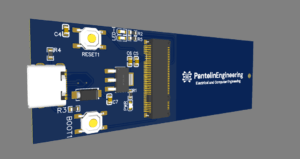
- The development board features the male part of an M.2 key connector.
- The programmer includes the female M.2 key interface, ensuring a snug, robust physical connection.
- This configuration minimizes the wear and tear associated with traditional pin headers or cables.
- ESP32-S3 Core:
- The board is powered by the ESP32-S3 module, which supports Wi-Fi and Bluetooth for IoT applications.
- It includes GPIOs that are routed through the M.2 connector for debugging and peripheral interfacing.
- USB-C Interface:
- A USB-C port is used for power delivery and direct communication with the programmer.
- Integrated circuitry ensures stable voltage regulation with components like the AMS1117-3.3 voltage regulator.
- Power Management:
- The system operates on a 3.3V logic level provided by the voltage regulator.
- Capacitors (10 µF and 100 nF) smooth power delivery for stable operation.
- Programming Support:
- The programmer handles USB-to-serial communication for firmware flashing.
- A RESET and BOOT button circuit simplifies the process of entering programming mode.
- Status LEDs:
- Integrated LEDs for power and programming status provide real-time feedback.
- GPIO-connected LEDs indicate the activity during operation.
Functional Workflow
- Hardware Connection:
- Plug the development board’s M.2 male connector into the programmer’s M.2 female interface.
- The keyed connector ensures alignment and proper pin mapping.
- Programming Mode:
- Use the buttons on the programmer to enter the ESP32-S3’s bootloader mode.
- The USB-C port on the programmer connects to a host PC, enabling firmware uploads via tools like ESP-IDF or Arduino IDE.
- Power and Status Feedback:
- The power LED confirms the device is powered.
- Activity LEDs indicate ongoing data transmission or programming.
- Detachable Design:
- Once programming is complete, the development board can be detached and deployed in its intended environment, maintaining a compact profile.
Applications
This programming system is ideal for:
- Prototyping and testing IoT devices.
- Compact embedded system designs where traditional headers are impractical.
- Environments requiring durable, high-frequency programming interfaces.
The innovative use of an M.2 connector ensures a reliable and compact programming solution that caters to the evolving demands of IoT and embedded development. This approach not only enhances usability but also improves the durability of the connections, making it a valuable addition to any developer’s toolkit.
Details
- Date: November 25, 2024
- Categories: PCB Layout and Design
- Project Files GITHUB